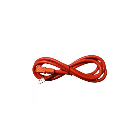
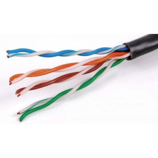
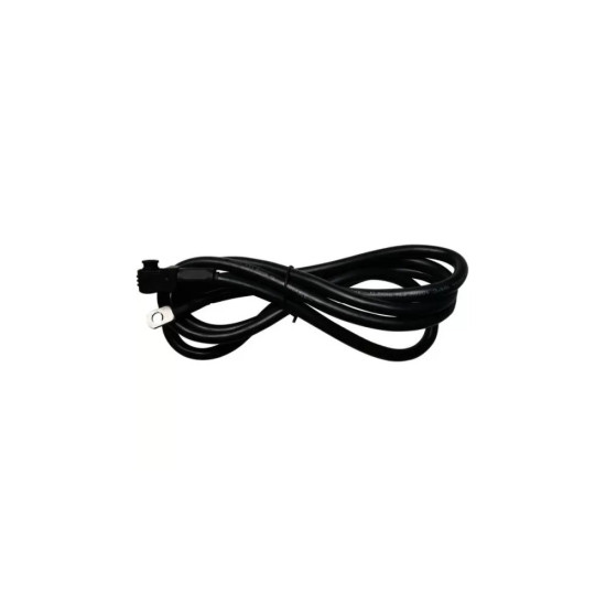
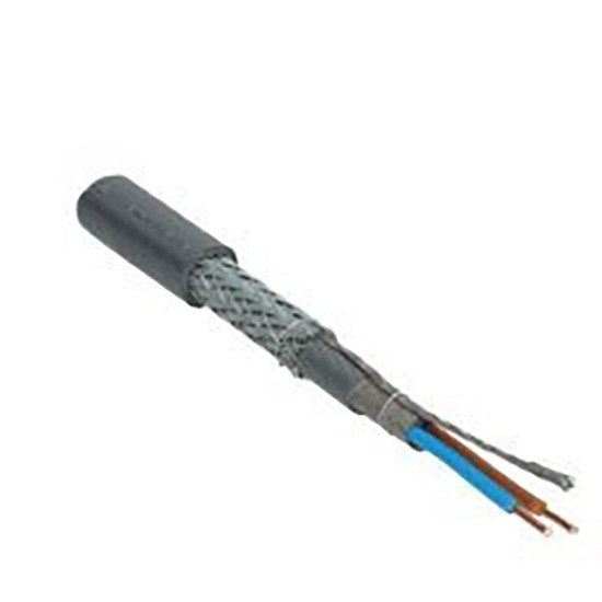
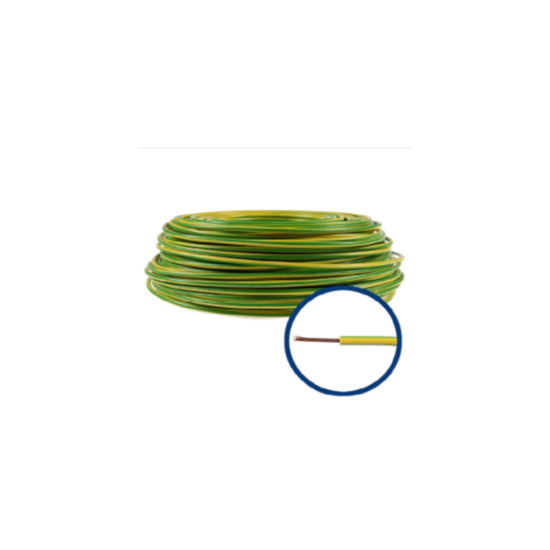
This is the power cable on the positive wire, the one marked in red, through which the energy actually passes from the battery to the inverter and back. It is a single-core cable of flexible stranded copper, easy to handle behind the equipment, with crimped ring lugs that are fastened with a screw onto the battery terminals. It is always installed together with its black counterpart, the two forming the complete power circuit of the storage system.
In a correctly built installation, the protection and isolation elements are also fitted on the positive wire: the DC fuse and/or the battery switch, between the battery and the inverter. They are what allow you to safely isolate the system for any intervention and protect it against a short circuit. The colour must be strictly respected, because a 48 V LiFePO4 battery delivers very high short-circuit currents, and reversing the polarity usually damages the inverter's DC input irreversibly. The cable is kept as short as possible and thick enough, because at 48 V the losses along the run are quickly felt in the delivered energy. Installation is done with the battery and the inverter disconnected and with the DC switch in the off position, and the lugs are tightened to the torque indicated by the battery manufacturer.
Single-core DC power cable on the positive pole, flexible stranded copper conductor, terminations with crimped ring lugs for the screw terminals of the battery, used between the positive terminal of the 48 V Pytes battery and the DC battery input of the inverter, paired with the black cable. The cross-section is chosen according to the maximum continuous charging and discharging current of the battery and the maximum battery current of the inverter, with a check of the voltage drop over the total length of the circuit. An insufficiently tightened contact increases the contact resistance and generates hot spots on the terminal, with progressive degradation in operation.
Who it suits
Required at any power connection between a 48 V Pytes battery and a hybrid inverter, including where the DC fuse or the battery switch is inserted on the positive pole.
Terms explained
- LiFePO4: The battery's chemistry type (lithium iron phosphate), known for a long service life and good thermal stability.
- DC fuse: A protection element that burns out intentionally and interrupts the circuit if a dangerously high current appears.
- Tightening torque: How tightly the screw is tightened, measured with a special wrench; neither too loose, nor too tight.
Technical specifications
| Type | Cablu de forta DC unipolar, polul pozitiv |
|---|
| Colour code | Rosu (pozitiv) |
|---|
| Conductor | Cupru multifilar flexibil |
|---|
| Terminations | Papuci inelari sertizati pentru bornele cu surub ale bateriei |
|---|
| Use | Intre borna pozitiva a bateriei Pytes de 48 V si intrarea DC de baterie a invertorului |
|---|
| Used in pair with | Cablul de forta pe polul negativ (negru) |
|---|
| Sizing criterion | Curentul maxim continuu de incarcare/descarcare al bateriei si curentul maxim de baterie al invertorului |
|---|
Recommended applications
- Power connection of the Pytes battery to a 48 V hybrid or off-grid inverter
- Routing through the DC fuse or the battery switch on the positive pole
- Residential storage systems with a low-voltage battery rack
- Replacement or rebuilding of the power connections when extending the battery bank
Technical details
Generic product — standard specifications
The cable provides the power link on the positive pole between the low-voltage Pytes battery and the DC battery input of the hybrid inverter. In construction it is a single-core cable with a flexible stranded copper conductor, fitted with crimped ring lugs for the screw terminals of the battery. It is installed together with the cable on the negative pole, the two forming the power circuit of the storage system.
The colour code on the battery side is red for positive and black for negative. The marking must be strictly respected, because 48 V LiFePO4 batteries have very high short-circuit currents, and reversing the polarity at connection usually damages the DC input stage of the inverter irreversibly.
In correctly executed installations, the protection and isolation element is also fitted on the positive pole - the DC fuse and/or the battery switch - between the battery and the inverter, so that the system can be safely isolated for interventions and protected against a short circuit. The cable cross-section is chosen according to the maximum continuous charging and discharging current of the battery and the maximum battery current of the inverter, and the length is kept as short as possible to limit the voltage drop, which is significant at the low voltage of 48 V.
During installation, the battery and the inverter are fully disconnected, and the battery's DC switch is set to the off position. The lugs are tightened to the torque specified by the battery manufacturer; a poorly tightened contact increases the resistance and generates hot spots on the terminal, with a risk of damage over time.