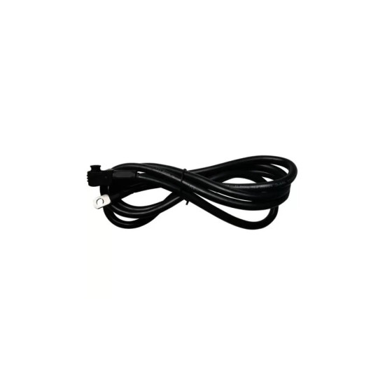
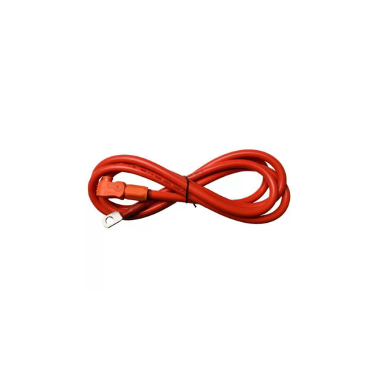
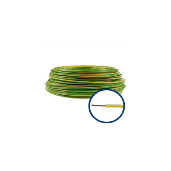
This is the thick cable through which the energy actually flows between battery and inverter, on the negative wire, the one marked in black. It does not carry data, but power, so it is the only place in the installation where the thickness of the cable directly affects how much energy reaches the house. It has a single copper conductor made of many thin strands, which makes it flexible and easy to bend behind the equipment, and at the ends it has crimped ring terminals, which are bolted onto the battery terminals. It must be used together with its red counterpart, on the positive pole.
The colours are not decorative: black means minus, red means plus, and reversing them when connecting usually destroys the input stage of the inverter, because a 48 V battery delivers very high short-circuit currents. The cable length is kept as short as possible: at 48 V, a few tenths of a volt lost along the route already mean percentages of the transferred power, that is energy paid for and not used. Installation is carried out with the battery and inverter completely disconnected and with the battery's DC switch in the off position. The terminals are tightened exactly as the battery manufacturer specifies: too loose means a hot contact and wear over time, too tight means a damaged thread and terminal. Otherwise the cable requires no maintenance, but it is worth checking the tightness at an annual service.
Single-pole DC power cable on the negative pole, flexible stranded copper conductor, terminations with crimped ring terminals for the screw terminals of the battery; the inverter end is connected with a lug or into the clamp terminal, depending on the model. It is used between the negative terminal of the 48 V Pytes battery and the battery DC input of the inverter, paired with the red cable. The sizing criterion is the maximum continuous charging and discharging current of the battery correlated with the maximum battery current of the inverter, taking the lower of the two as reference, with verification of the voltage drop on the round-trip circuit.
Who it suits
Needed for any installation or repair of the power connection between a 48 V Pytes battery and a hybrid or off-grid inverter, including when extending the battery bank.
Terms explained
- Ring terminal: The ring-shaped metal terminal at the end of the cable, which is bolted directly onto the battery terminal.
- Stranded conductor: A cable made of many thin strands instead of one thick one, so that it can be bent easily without breaking.
- Voltage drop: The volts lost along the way, in the cable; the thinner or longer the cable, the more you lose.
Technical specifications
| Type | Cablu de forta DC unipolar, polul negativ |
|---|
| Colour code | Negru (negativ) |
|---|
| Conductor | Cupru multifilar flexibil |
|---|
| Terminations | Papuci inelari sertizati pentru bornele cu surub ale bateriei |
|---|
| Use | Intre borna negativa a bateriei Pytes de 48 V si intrarea DC de baterie a invertorului |
|---|
| Used in pair with | Cablul de forta pe polul pozitiv (rosu) |
|---|
| Sizing criterion | Curentul maxim continuu de incarcare/descarcare al bateriei si curentul maxim de baterie al invertorului |
|---|
Recommended applications
- Power connection of the Pytes battery to a 48 V hybrid or off-grid inverter
- Residential storage systems with a low-voltage battery rack
- Replacement of damaged or undersized battery cables
- Reconfiguration of a storage system when extending it with additional modules
Technical details
Generic product — standard specifications
The cable provides the power connection on the negative pole between the low-voltage Pytes battery and the battery DC input of the hybrid inverter. It is a single-pole cable with a flexible stranded copper conductor, terminated with crimped ring terminals that are bolted onto the screw terminals of the battery; the inverter end is connected either with a lug as well, or into the inverter's clamp terminal, depending on the model. It must be used in pair with the cable on the positive pole.
On the battery side the colour code is black for negative and red for positive. Observing this convention is not cosmetic: 48 V lithium-iron-phosphate batteries deliver very high short-circuit currents, and a polarity reversal when connecting usually destroys the input stage of the inverter and can trigger the BMS protections or even internal damage to the module.
The correct sizing of this cable is done according to the maximum continuous charging and discharging current of the battery and according to the maximum battery current of the inverter, taking the lower of the two values as the design reference. At 48 V, a voltage loss of a few tenths of a volt on the cable already means percentages of the transferred power, so the cross-section and length are chosen so that the voltage drop over the whole round-trip circuit stays within small limits.
Installation is carried out with the battery and inverter disconnected, with the battery's DC switch in the off position. The terminals are tightened to the torque indicated by the battery manufacturer - insufficient tightening increases the contact resistance and leads to heating of the terminal, while excessive tightening can damage the thread and the terminal.