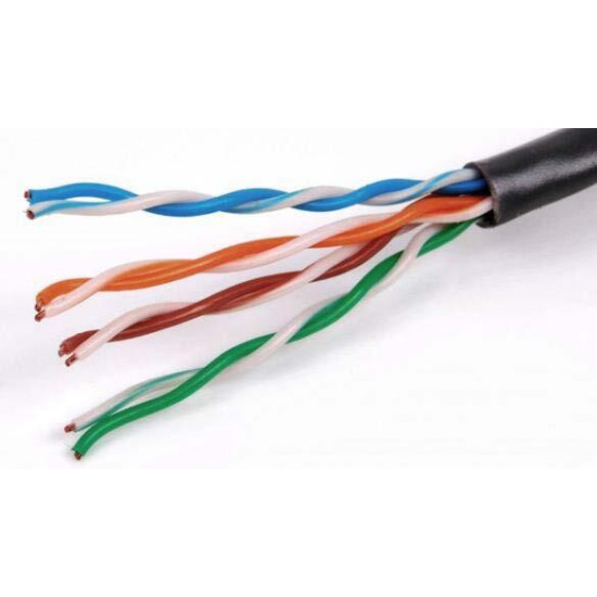
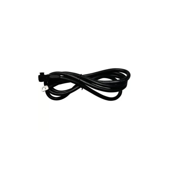
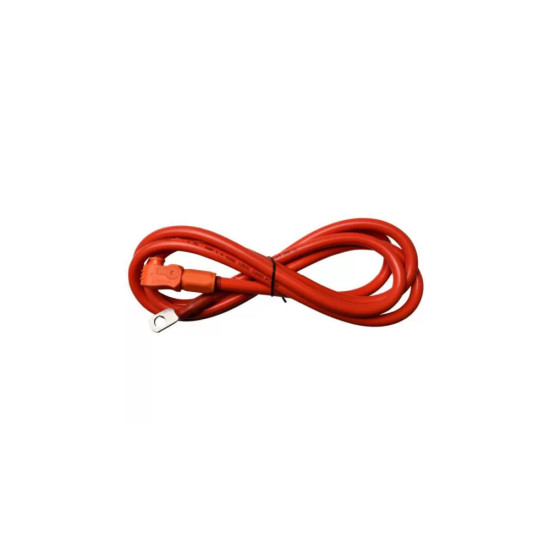
This is the cable through which the battery tells the inverter how it feels. It looks exactly like an internet cable, with RJ45 plugs at both ends, but its wires are arranged specially for the battery-inverter pair, so it cannot be replaced with an ordinary network cable bought from a shop. One end goes into the communication port of the battery, the other into the battery port of the inverter, usually marked BMS or Battery CAN Bus.
With this cable fitted, the inverter receives in real time the state of charge of the battery, the voltage, the current, the cell temperatures and the charge and discharge limits, so it knows exactly how much more it can take and how much more it can give. Without it, the inverter works to fixed, estimated voltage thresholds: the battery is never fully used, it is charged incorrectly at the ends and ages faster. The Pytes V5 B2I version is 3.5 m long, enough for the usual installations in which the battery rack and the inverter are on the same wall. If you have several batteries, this cable is connected only to the main (master) battery, the remaining modules being daisy-chained with their own link cables. It requires no maintenance: once correctly connected, it stays there.
The low-voltage Pytes batteries expose several RJ45 ports: CAN, RS485 and RS232 for service. The choice between the CAN port and the RS485 port is made according to the protocol supported by the inverter, and the pinout differs between inverter brands, which is why the B2I cable is dedicated to a specific battery-inverter combination. Compatibility with low-voltage Pytes batteries (E-BOX 48100R, V5 series) connected to inverters that support the Pytes protocol. In parallel setups, the communication towards the inverter is taken exclusively from the master unit, the daisy chain is made from Link 1 of one battery to Link 0 of the next, and the addressing of the modules is set with the DIP switches.
Who it suits
Necessary for anyone installing a Pytes battery with a hybrid inverter and wanting the system to use the whole capacity of the battery, not just part of it.
Terms explained
- BMS: The brain of the battery: the electronic module that supervises its cells and decides how much it can safely charge or discharge.
- SOC (state of charge): The percentage of energy remaining in the battery, just like the battery indicator on a phone.
- Closed-loop communication: The battery and the inverter exchange data continuously, instead of the inverter guessing the state of the battery by itself.
Technical specifications
| Type | Cablu de comunicatie baterie-invertor (B2I), RJ45 - RJ45 |
|---|
| Protocols available on the battery | CAN si RS485 (porturi RJ45 dedicate); suplimentar RS232 pentru service |
|---|
| Length (Pytes V5 B2I version) | 3,5 m |
|---|
| Connection | Port CAN sau RS485 al bateriei master -> port comunicatie baterie (BMS/Battery CAN Bus) al invertorului |
|---|
| Compatibility | Baterii Pytes de joasa tensiune (seria E-BOX 48100R, V5) cu invertoare care suporta protocolul Pytes |
|---|
| Function | Transmitere SOC, tensiune, curent, temperatura si limite de incarcare/descarcare catre invertor |
|---|
Recommended applications
- Enabling closed-loop communication between the Pytes battery and the hybrid inverter
- Residential storage systems with a hybrid inverter and a Pytes battery rack
- Configurations with several Pytes modules in parallel, connected to the master unit
- Remote monitoring of the battery status through the inverter interface
Technical details
Series-level specifications — valid for the product family
The communication cable makes the data link between the BMS of the Pytes battery and the hybrid inverter. It is an RJ45 - RJ45 cable that is connected at one end into the communication port of the master battery (CAN or RS485, depending on the protocol supported by the inverter) and at the other end into the port dedicated to the battery on the inverter, usually called Battery CAN Bus or BMS. The Pytes V5 B2I (battery-to-inverter) version is 3.5 m long, enough for the usual installations in which the battery rack and the inverter are on the same wall.
The low-voltage Pytes batteries expose several RJ45 ports: RS232, RS485 and CAN. The CAN port transmits the battery information on the CAN protocol, and the RS485 port on the RS485 protocol; the choice is made according to the type of communication supported by the inverter. It is important to note that the pinout differs between inverter brands, which is why the B2I cable is dedicated to a specific battery-inverter combination and cannot be replaced with an ordinary Ethernet patch cord.
The functional role of the cable is closed-loop communication. Through it the inverter receives from the BMS the state of charge (SOC), the voltage and current of the pack, the cell temperatures and the instantaneous charge and discharge limits. Without this link the inverter works in fixed voltage mode, with estimated thresholds, which leads to incomplete use of the capacity, to incorrect charging at the ends of the range and to a shorter battery life.
In configurations with several batteries in parallel, the inverter-battery communication cable is connected only to the master unit, the remaining modules being daisy-chained through the link cables (Link 1 of one battery to Link 0 of the next), and the addressing is set with the DIP switches on each module.