K2 Systems
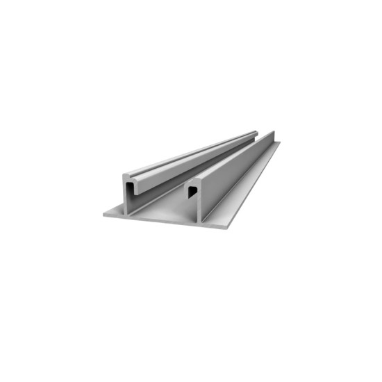
Basic Rail 22 - K2 mounting rail 4800 mm
It supports the panels on a sheet metal roof without loading it: a 4.8 m aluminium profile that weighs about 3.1 kg and raises the modules by only 22.5 mm.
161,39 RON incl. VATexcl. VAT: 133,38 RON
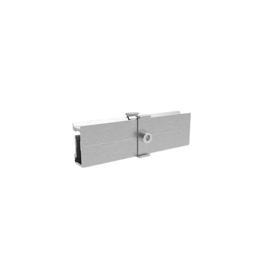
Joins two rail bars end to end, so you can obtain rows longer than the standard bar and also use the leftover ends, with less material waste.
Rails are delivered in standard lengths, but panel rows are often longer than a single bar. The connector, also called a splice, is the part that joins two bars end to end, as if you were extending a ruler. The result is a continuous row, not two pieces placed next to each other.
Its role is not only to hold the bars together, but to transfer the loads from one bar to the other, so that the spliced rail behaves as closely as possible to a whole bar. For this reason the position of the joint is not chosen at random: system manufacturers require the splice to be placed next to a support point or in an area with reduced bending moment, and for long spans some systems also provide an expansion gap, because aluminium changes its length with temperature. A practical advantage is that you can also make use of the bar ends left over from cutting, so the amount of discarded material decreases. Be careful though: the connector must be bought strictly for the rail profile used, because the channel geometry differs between manufacturers and even between series of the same manufacturer.
Internal splice profiled to the geometry of the channel, inserted halfway into each end and locked with screws, or external splice screwed over the joint, depending on the system. Extruded aluminium material, with stainless steel locking screws; some versions have teeth that pierce the oxide layer and provide electrical continuity between sections, useful for the equipotential bonding of the metal structure. The position of the joint is set according to the system supplier's instructions, in an area with reduced bending moment, with an expansion gap provided for long span lengths.
Suitable for installations with long panel rows, on halls or industrial roofs, and for assemblies where the leftover bar ends are to be used.
| Type | Conector (eclisa) de innadire pentru sine de aluminiu |
|---|---|
| Material | Aluminiu extrudat, suruburi de blocare din otel inoxidabil |
| Mounting | Se introduce in capetele a doua sine si se blocheaza cu suruburi |
| Function | Continuitate mecanica si transmiterea eforturilor peste imbinare |
| Compatibility condition | Se alege pentru profilul exact de sina folosit |
Generic product — standard specifications
The rail connector is the part that joins two aluminium rail sections end to end, allowing continuous rows longer than the standard bar delivered. Structurally it is an internal splice, profiled to the geometry of the rail channel, which is inserted halfway into each end and locked with fixing screws, or an external splice screwed over the joint, depending on the system used.
The role of the connector is to transfer the axial loads and the bending moment across the joint gap, so that the spliced rail behaves as closely as possible to a continuous bar. For this reason, the position of the joint is not arbitrary: system manufacturers require the splice to be placed near a support point or in an area with reduced bending moment, and some systems also provide an expansion gap for long span lengths, to take up the dimensional variations of aluminium with temperature.
The usual material is extruded aluminium, with stainless steel locking screws; some versions are provided with teeth that pierce the oxide layer, which also provide electrical continuity between sections, useful for the equipotential bonding of the metal structure. The connector must be chosen strictly for the rail profile used, because the channel geometry differs between manufacturers and between series.
It supports the panels on a sheet metal roof without loading it: a 4.8 m aluminium profile that weighs about 3.1 kg and raises the modules by only 22.5 mm.
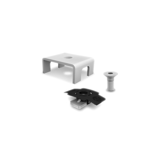
It prevents the rail from migrating on the roof: a fixed point that locks the BasicRail 22 bar and splits the expansion towards both ends. K2 BasicLock 22 set, code 1003558.
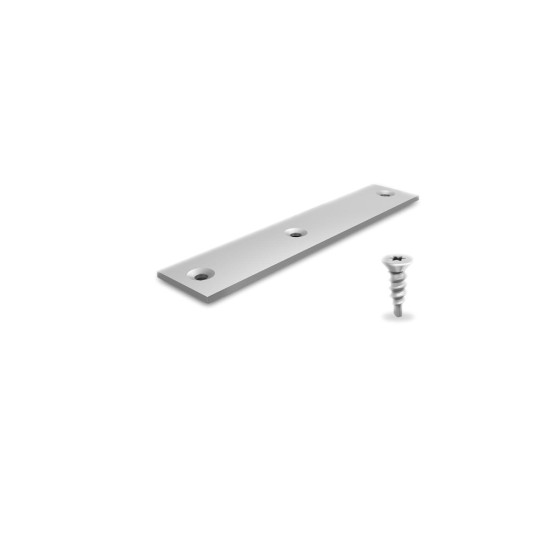
It joins two rails end to end so that you get a continuous row, without cutting bars. Aluminium and A2 stainless steel, 3 fixing holes, Torx T25 screws included.
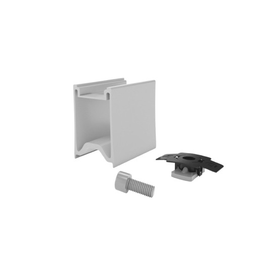
Lifts the panels off the rail so air can circulate underneath: cooler modules lose less power, and there is room for microinverters below. K2 RailUp set, code 2003191.